Centrifugal Pump
Pumps water up in elevation while maximizing flow rate
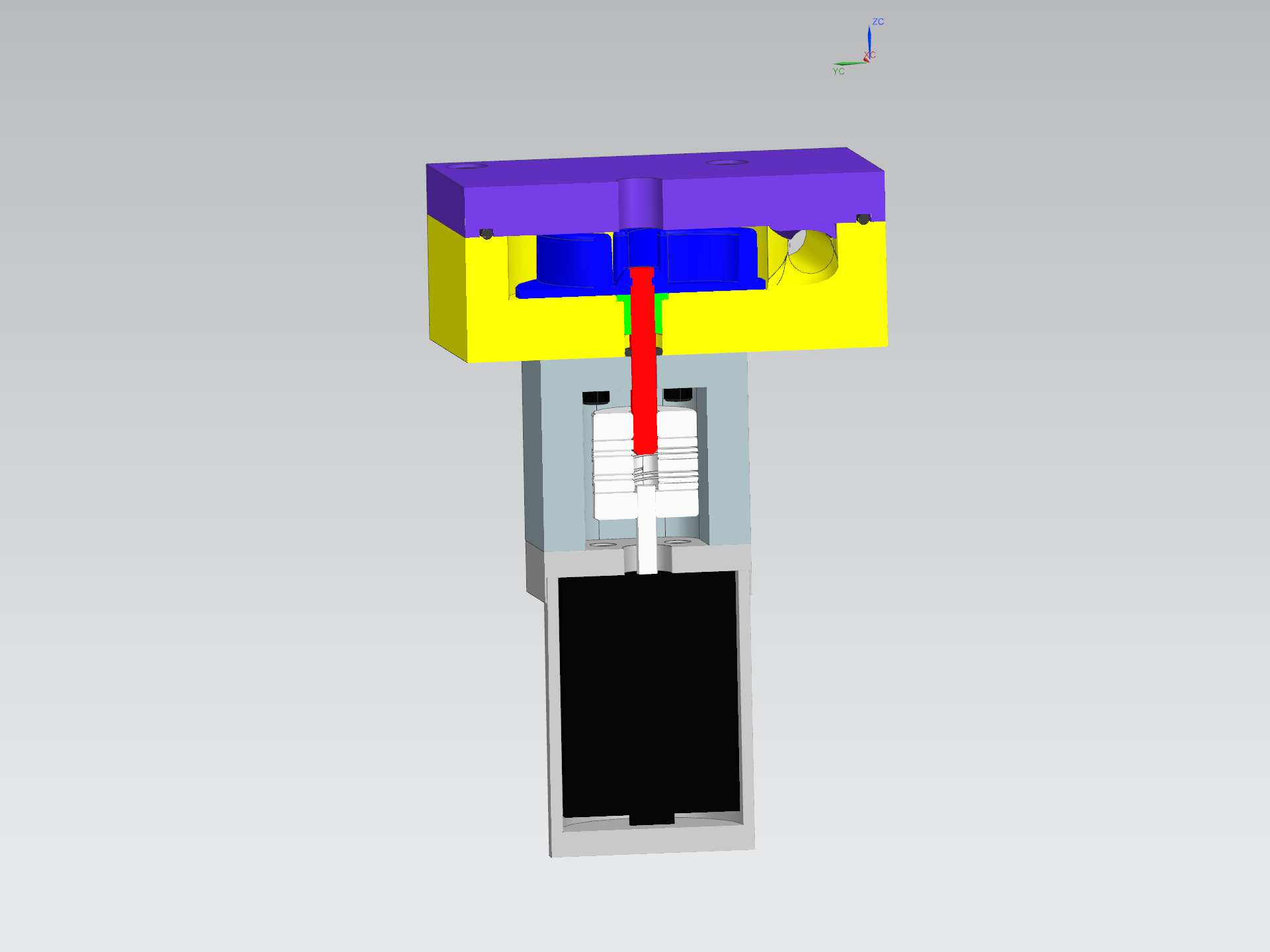
The goal of this project is to pump water up an effective difference in elevation of 1m while maximizing the flow rate. First, a 3D model of the centrifugal pump was designed in Siemens NX. A smooth ramp was designed at the water's exit of the casing to minimize the loss of energy caused by hitting a flat wall. The parts designed for fabrication along with the assembly of the pump are illustrated below.

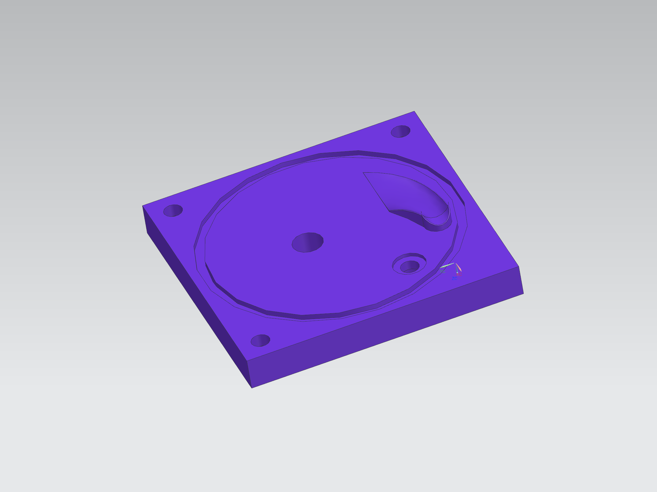
The parts that need to be machined are the pump's casing (comprised of the base and the cover) and the impeller's molds. The CNC tool paths for all the machined parts are created and tested in simulation. An example for the tool path of the base of the casing is shown below. The parts are machined on a Fryer MC-15 CNC machine.
Once the parts are machined, the impeller is made through injection molding of polyethylene plastic. The fabricated parts are then measured using a micrometer, a caliper, pin gages and a granite inspection table paired with a height gage for quality control. Then, the pump is assembled and prepared for testing. The experiment consists of pumping water from a lower reservoir to a higher reservoir for 1 minute and measuring the flow rate. The effective difference in elevation of the reservoirs is 1m. A motor keeping a constant angular velocity of 3500 rpm is used to rotate the impeller and drive the pump. In 30 seconds of use, the pump had carried 11 L of water up the pipe, therefore a flow of 22 L/min was observed. The video at the top of the page shows the experimental setup and the centrifugal pump in action.